Objectives:
- To understand what Thermistors and Light Dependent Resistors are;
- Be able to describe an experiment to obtain the characteristics of a thermistor
- To understand the variation of resistance of metals and semiconductors with temperature.
Ohmic conductors

In an ohmic conductor, free electrons carry the current when a potential difference is applied across it. When the physical conditions stay constant, current will be proportional to the voltage and this will equal ratio $latex \frac{V}{I} which is the resistance R of the component.
Non-Ohmic conductors

Across a non-Ohmic conductor such as a filament lamp, when the p.d. increases, the current flow also increases to start with (as we’d expect). An increase in current results in an increase in ‘collisions’ between the electrons and the ions, meaning the ions in the lattice vibrate more rapidly, thereby heats up the conductor. This in turn leads to a greater resistance slowing the flow of electrons so a smaller current flows.
Semiconductors

In semiconductors as the energy given increases, more free electrons are let free and so a current increases and the resistance goes down. In light dependent resistors, this energy is light and in thermistors it is heat.
Thermistors
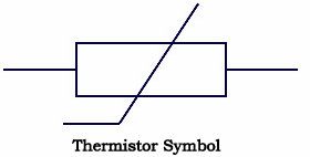 Thermistors are inexpensive, easily-obtainable temperature sensors. They are easy to use and adaptable. Circuits with thermistors can have reasonable output voltages – not the millivolt outputs thermocouples have. Because of these qualities, thermistors are widely used for simple temperature measurements. They’re not used for high temperatures, but in the temperature ranges where they work they are widely used.
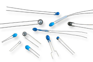
Thermistors are temperature sensitive resistors. All resistors vary with temperature, but thermistors are constructed of a semiconductor material which behave differently to normal metallic conductors. However, unlike most other resistive devices, the resistance of a thermistor decreases with increasing temperature. This is due to the properties of the semiconductor material that the thermistor is made from. For some, this may be counterintuitive, but it is correct. Here is a graph of resistance as a function of temperature for a typical thermistor. Notice how the resistance drops from 100 kW, to a very small value in a range around room temperature. Not only is the resistance change in the opposite direction from what you expect, but the magnitude of the percentage resistance change is substantial.

Positive temperature coefficient (PTC) thermistors
Positive temperature coefficient thermistors do exist but are typically made from just normal conductors, like a metal wire. As the temperature increases, the ion lattice vibrates more and so the resistance increases and the current decreases. Due to this the relationship resistance has to temperature is different to an NTC thermistor, as can be seen here;
 PTC thermistor – positive temperature coefficient, and so has a positive gradient on a resistance-temperature graph.
NTC thermistor – negative temperature coefficient, and so has a negative gradient on a resistance-temperature graph.
Light Dependent Resistors
Light Dependent Resistors, otherwise known as LDRs, follow the same principle as thermistors in the sense that they are made from a semiconductor material. Instead of a change in temperature that varies the resistance, it is the light that is incident upon in.
The graph for a thermistor and LDR are very similar, but we change the x-axis to account for a change in light intensity instead of temperature, as follows;

Further reading:
- Investigate what is meant by a superconductor and its applications.
- ‘Resistivity and Temperature Coefficient of Thin Metal Films with Rough Surface’, Japanese Journal of Applied Physics by Yoshikatsu Namba, which is available here as a PDF file – Munoz_RC
You must be logged in to post a comment.