Objectives:
- To identify series and parallel circuits
- To understand where an ammeter needs to be placed in a circuit and why
- To understand where a voltmeter needs to be placed in a circuit and why
Circuits
A circuit is a complete path around which electricity can flow. It needs to include a source of energy such as a battery of power supply. Materials that allow electric current to pass through them easily are called conductors, these can be used to link the positive and negative ends of a battery, creating a complete circuit.
In an open or broken circuit, there is a break along the line and the current stops. In a closed or complete circuit electric current can flow. When electric current flows it can be used by electrical appliances such as light bulbs or buzzers.
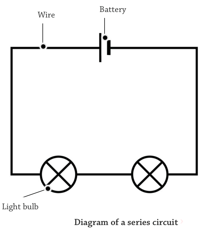
Series Circuits
A series circuit is one in which all components including the power source are connected in one loop. Here is an example of a series circuit with its associated circuit diagram;

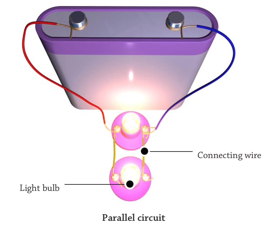
 Parallel Circuits
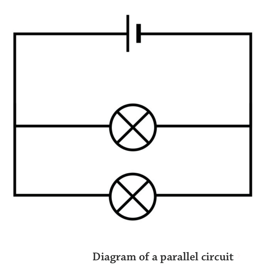
A parallel circuit is one in which some or all of the components including the power source are connected in two or more loops. Here is an example of a series circuit with its associated circuit diagram;
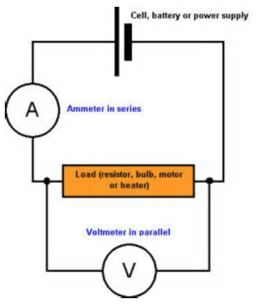
An ammeter, a device that measure the rate of flow of charge (current), needs to be positioned in such a place that allows the charge to flow through it – so that the meter can measure (or ‘count’) the amount of charge that flows through it. Therefore an ammeter needs to be placed in series.
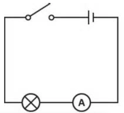 The ammeter itself should not affect the flow of charge itself, therefore it needs to have no resistance. Inevitably, for the ammeter to work it will have some resistance (but it should be negligible (0 Ω). Here is a diagram showing where an ammeter should be positioned;
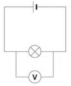
A voltmeter measures the difference in potential from one point in a circuit to another. In order to do this it needs to be connected to two different points in a circuit, therefore needs to be placed in parallel to a component that it is measuring.
With both an ammeter and a voltmeter placed in a circuit, the circuit should look like the following;
Further reading:
- http://www.physicsclassroom.com/class/circuits/Lesson-4/Series-Circuits -Try the questions at the bottom of this site too!
You must be logged in to post a comment.