Objectives:
- To understand how the total resistance of a circuit is affected by multiple resistors in series
- To be able to calculate the total resistance of two or more resistors in series using
- To understand how the total resistance of a circuit is affected by multiple resistors in parallel
- To be able to analyse of circuits with components, including both series and parallel


Resistors are components that increase the resistance along a path of a circuit. They can be made of a number of different materials including types of alloys, carbon or a material coated in ceramic.
A metal wire has a resistance, as discussed in previous sessions – link, there are ions held in a fixed lattice in which the flow of electrons needs to pass by.

If the length of the wire were to double, there would be twice as many ions to pass and so there would be twice as much resistance.
Resistors in Series
Resistors placed in series increase the total resistance of the circuit in the same way that increasing the length of the wire increases the total resistance.

Take this circuit, if each resistor had a resistance of 

If each resistor has a different value of resistance e.g. 


The following equation can be used to calculate the total resistance of a series of resistors in series:
This equation can be proved to work experimentally but it can also be derived by using Kirchhoff’s two laws, try it for yourself, a full derivation can be found here – Deriving the Equation for Resistors in Series.
You will need to be able to use this equation both on its own but also while working out the total current in a circuit using a given voltage. For example, if you are given a voltage of 6.0 V and a selection of 10 Ω resistors. With 1 of those 10 Ω resistors connected in series to the voltage source, the current can be determined by using;


If the question were then changed such that there were three resistors in series but the same voltage and you were asked for the current. You would first need to add together all of the resistors to find the total resistance and then enter this into 


In this case, with three times the resistance the current decreases by a factor of three.
Resistors in Parallel
Resistors placed in parallel decrease the total resistance of the circuit. The reason for this is that there are more paths for the charged particles to travel down. Take this circuit for instance;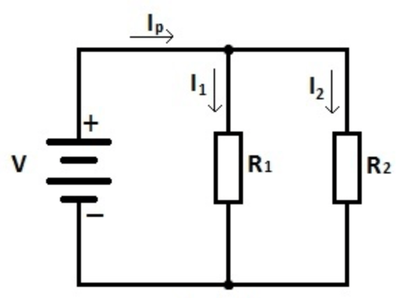
- If we initially only had resistor
in place and this had an an extremely high resistance, say
, then the electrons would struggle to flow through it and hence around the circuit at all.
- If resistor 2 was then inserted into the position shown and has a low resistance, say
, then the electrons have the ability to travel down this path instead and hence can allow a current around the circuit.
- Inserting the second resistor in parallel has allowed more current to flow and thus has decreased the overall resistance of the circuit.
Take the following circuit;
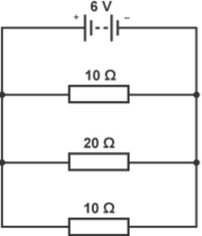
Even though there are multiple resistors, most of which are greater than 10 Ω (as per the question above on series circuits), the total resistance will decrease because there are more paths for the electrons to go down.
There is an equation for resistors in series, but it is not needed in GCSE. If you want to know more about the equation for resistors in parallel look at the A level page – link.
Questions:
Three resistors, two with a resistance 

i) all connected in series together.
ii) all connected in parallel to one another
iii) the two
iv) the two
Hint: Draw each circuit and try calculating the overall resistance of certain parts separately.
Answers:
If you do not obtain the following answers try again until you do;
i)
ii) The total resistance will be less than the smallest resistor value;
iii) The total resistance of the two 25 Ω resistors in 50 Ω, but this 50Ω is in series with another 50 Ω resistors. This means the total resistance must be 
iv) The total resistance of the part in parallel is 


– – – – – – – – – – – – – – –

How many resistor combinations can be made using three identical resistors each with a resistance of 
Repeat the question but with four
Answers can be found using this link
Further reading:
- Try to find examples of applications in which resistors are connected in series or in parallel, such as lighting circuits, Christmas tree lights, car window heaters and car headlamps.
- A history of electricity (The intellectual rise in electricity) from antiquity to the days of Benjamin Franklin by Benjamin Park – link
- Introductory electronics texts on how to build series and parallel circuits would be helpful – potential link
You must be logged in to post a comment.