Objectives:
- To understand and be able to use and apply Fleming’s left-hand rule
- To appreciate the force acting on a current-carrying conductor and what is attributed to
- To be able to apply and use the equation
- Experimentally understand the techniques used to determine the uniform magnetic flux density between the poles of a magnet using a current-carrying wire and digital balance
- To learn the unit of magnetic flux density and be able to define it; the unit tesla

In order to appreciate the content on this page you aught to have a good understanding of magnetic fields due to permanent magnets as well as magnetic fields due to current carrying conductors.
Since magnetic fields cannot cross over one another but instead superimpose and constructively or destructively interfere, what do you suppose happens if a current carrying conductors was placed inside a permanent magnets magnetic field?
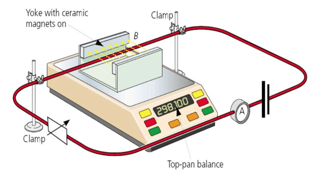
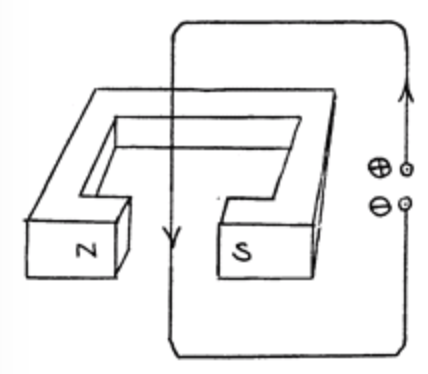
The question can be answered and investigated by placing a yolk with magnets attached to it on a top pan balance as shown in the diagram below. This type of magnet results in one side having a north pole and the other having the south pole;
 By placing a current carrying conductor within the field of the permanent magnet we may be able to observe (or see the effect of) an interaction between the two fields. Below shows the independent magnetic fields of both the permanent magnet and the current carrying conductor;
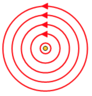
 So lets assume the current is coming out of the page, thereby creating an anticlockwise magnetic field
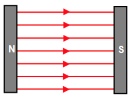
The permanent magnet has a uniform magnetic field going to the right.
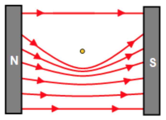
If the current carrying conductor were to be placed inside the permanent magnetic field we will hopefully see how the fields superimpose;
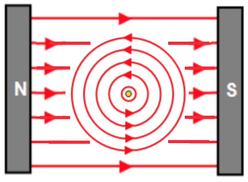
Since the magnetic fields do not overlap, you will notice that above the wire the two magnetic fields destructively interfere and below the wire they constructively interfere. This causes field lines to compress under the wire and for there to be a smaller magnetic flux density above the wire;
 Because the magnetic field line below the wire have been compressed they repel one another and end of forcing the wire to move up into the reduced magnetic field zone. This is the catapult effect as there is an electromagnetic force exert on the wire. It is also known as the motor effect because we can now use electricity to get an item to move – this is the start of how a motor actually works.
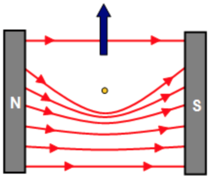 The direction of this force is hopefully clear from the diagrams above, however there is an easier way to determine the direction of the force acting on a wire when in a magnetic field. This is known as Fleming’s left hand rule.
Fleming’s left hand rule allows us to determine the direction in which a current carrying conductor will be forced to move in when placed in a magnetic field. This force is exerted when the current is travelling perpendicularly to the magnetic field, in turn the force the is then exerted perpendicularly to both the magnetic field and the direction of the current. The following image shows you how you would use your hand to demonstrate this;
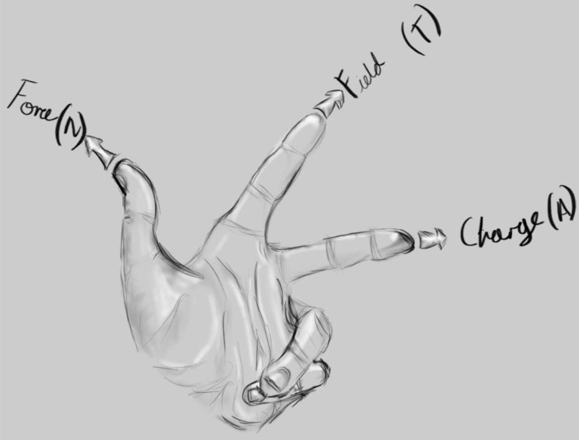
Using your left thumb, index finger and second fingered and making them all at right angles to one another.
The thumb represents the direction of the force on the current carrying conductor and therefore is also the direction of motion, the first finger represents the direction of the magnetic fields and the second finger represents the direction of the conventional current. There are ways to remember this, one is:
- Thumb = motion
- First finger = magnetic field
- Second finger = conventional current
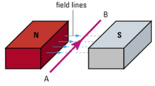
In which direction will the wire be forced to move in the following diagram? Use your left hand – don’t be afraid to look like a bit of a muppet (even in your exams!).
Try the next two;
Experimenting with this magnetic force
How is the force affected by the current?
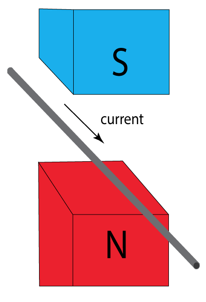
By using the setup above, if we place the yoke magnet onto a balance with a current carrying wire clamped and held between the magnets, the wire will experience a force which relates to the current it carries. By measuring the change of mass on the scale, we can calculate the force exerted on the wire. For example, if the force acts upwards, the mass registered on the scale will be less than before the current was flowing. That difference can be multiplied by the gravitational field strength to find the force (or weight). Below is a table of results created from an experiment carried out to determine how changing the current affects the force exerted.
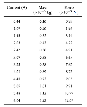
This set of data, enables the following graph of current versus force to be drawn;
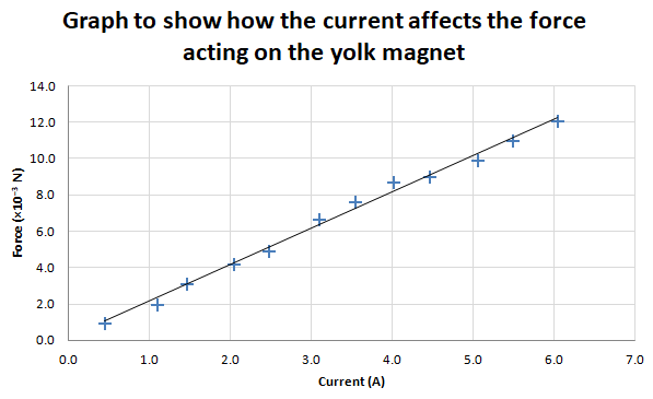
If you extrapolate this line backwards you can see that it will pass through the origin. This should make sense because with no current flowing in the solenoid, there would be no magnetic field around the wire and therefore no interaction between the two magnetic fields, meaning no force exerted.
We can also then state that the force is directly proportional to the current;

How is the force affected by the length of wire within the magnetic field?
By placing the apparatus on a balance again, the current carrying conductor will experience a force which relates to the current it carries. To vary the length of wire inside the permanent magnetic field, the wire needs to loop around in circles. With two pieces of wire within the permanent magnetic field, we can say that double the length of wire is interacting with the field and a different force is exerted. The wire cannot just be flipped (or reversed in on itself) as the current would be in the opposite direction and then the magnetic field in each will oppose each other rather than constructively superimpose with each other. The table below shows an example set of data for this experiment;
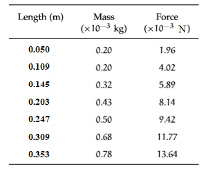
This set of data, enables the following graph of length versus force to be drawn;
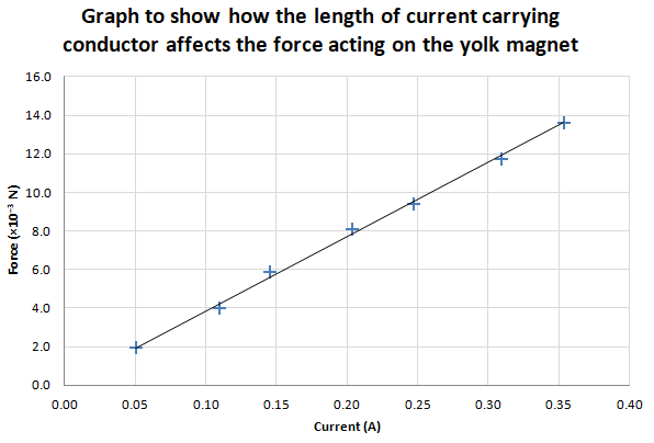
If you extrapolate this line backwards you can see that it will pass through the origin. This should make sense because with no length of wire (or current carrying conductor) within the permanent magnetic field, there would be no interaction between the two magnetic fields, meaning no force exerted.
We can also then state that the force is directly proportional to the length of current carrying conductor;

The following video summarises this experiment nicely:
[embedyt] https://www.youtube.com/watch?v=Ar51rxfXrmU%5B/embedyt%5D
Now we know that the electromagnetic force is directly proportional to both the length of the current carrying conductor within the field and the magnitude of the current. So we can write:

We can therefore write;

The constant of proportionality, 

where;


This equation, rearranged for

Magnetic flux density is the force per unit current per unit length when the direction of current is perpendicular to the direction of the magnetic field.
Defining the Tesla
The Tesla is the unit given to the magnetic flux density. Its true definition is given by using that of magnetic flux density.
One Tesla is equivalent to one Newton acting per one Ampere per one metre of length (when the current is perpendicular to the magnetic field). As a formula this can be written as;

Try some questions based on these principles:
- IsaacPhysics – Force acting on a current carrying conductor
You must be logged in to post a comment.