Take the following circuit that shows a system which can be used to both charge and discharge a capacitor through a resistor 
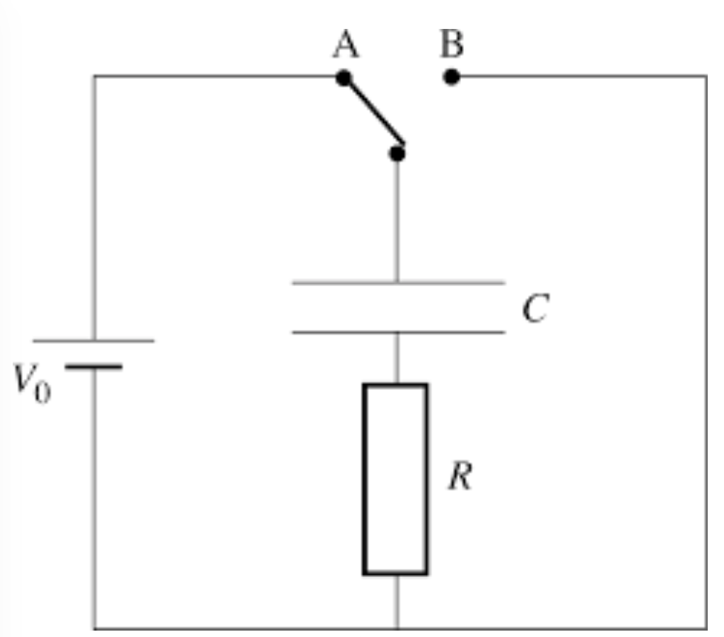
Only focussing on the right hand side of this circuit (with the B terminal connected to the capacitor and using Kirchhoff’s 1st law), we can write;

where


A discharging capacitor has charge flowing from the plate in which it has excess electrons to the plate where it has an absence of electrons. As such, as the capacitor discharges it loses its charge over time. The current therefore decreases over time because there is less charge being able to flow around the circuit. Therefore the current flow decreases over time. Since 

Since, by definition 

Substituting equations 


Rearranging to give 


In order to integrate and remove the ‘rate of change of time’, so exact values for charge at a particular time frame can be given;

Putting the equation into this form tells us to integrate the equation. If the capacitor is to be charged from a start time of 


This equation becomes;
![[\ln(q)]_{q_{0}}^{q} = [\frac{t}{RC}]_{0}^{t}](https://s0.wp.com/latex.php?latex=%5B%5Cln%28q%29%5D_%7Bq_%7B0%7D%7D%5E%7Bq%7D+%3D+%5B%5Cfrac%7Bt%7D%7BRC%7D%5D_%7B0%7D%5E%7Bt%7D+&bg=f0eeec&fg=222222&s=0&c=20201002)

Using log rules whereby 

Taking the exponential of both sides gives;


Rearranging for q gives;

where


Dividing by C gives;

Since 

where


A graphical representation of this equation would give;
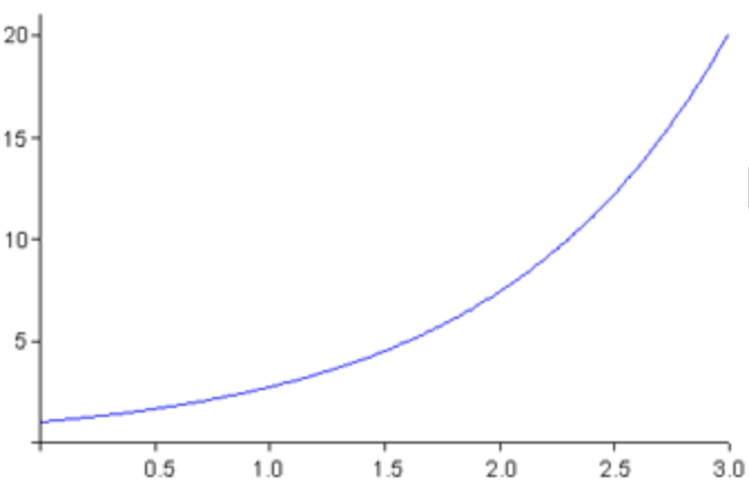 where voltage would be on the y-axis and time on the x-axis.
This goes against what we should expect – we should see that the voltage decreases as it is discharge.
When fully charged, the capacitor should hold a maximum p.d,
Where the voltage decreases such that at time 
So what is wrong with the derivation above?
It is something to with this section right at the start;
If you look at the circuit diagram, if this capacitor were to be charged the electron flow around the left hand side of the circuit would be anticlockwise. This would result in electrons being deposited on the lower side of the capacitor and therefore an absence of electron on the top plate (positive charge);
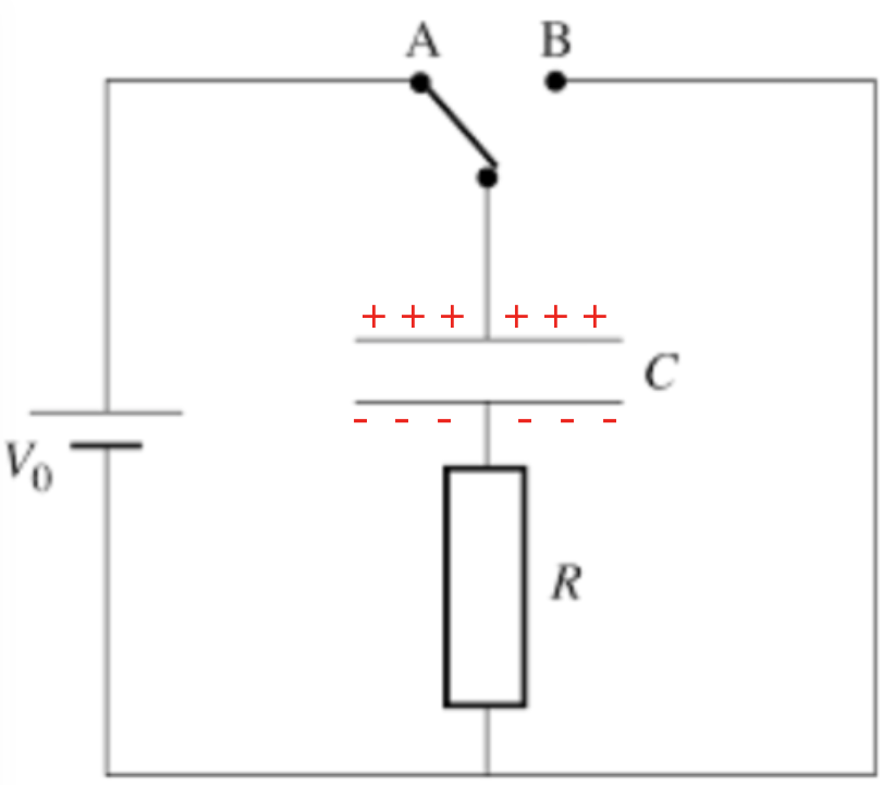
So this is the circuit we have before discharge takes place.
If the switch were flicked such that the B terminal were connected to the capacitor instead of the A terminal, the capacitor would discharge (as we saw previously) around the right hand side of the circuit.
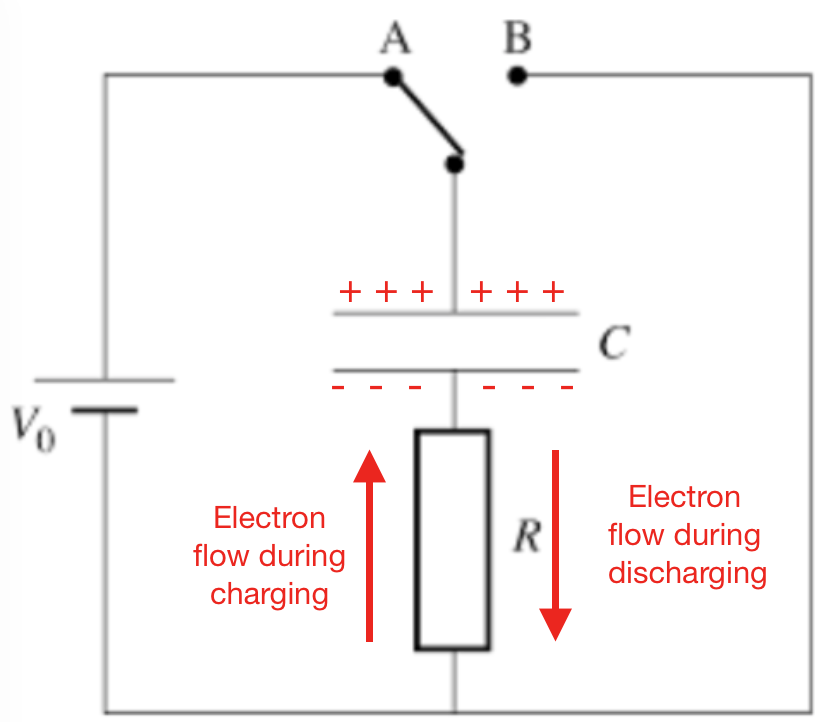
The electrons would then flow back through the resistor (in the opposite direction they took to when they were charging.
The electron flow has reverse.
With this in mind the equation


That negative changes the whole equation, so lets substitute it back in and re-derive the discharging of a capacitor equation;
The discharging capacitor has charge flowing from the plate in which it has excess electrons to the plate where it has an absence of electrons. As such, as the capacitor discharges it loses its charge over time. The current therefore decreases over time because there is less charge being able to flow around the circuit. Therefore the current flow decreases over time. Since

Since, by definition

Substituting equations


Rearranging to give


In order to integrate and remove the ‘rate of change of time’, so exact values for charge at a particular time frame can be given;

Putting the equation into this form tells us to integrate the equation. If the capacitor is to be charged from a start time of

This equation becomes;
![[\ln(q)]_{q_{0}}^{q} = [-\frac{t}{RC}]_{0}^{t}](https://s0.wp.com/latex.php?latex=%5B%5Cln%28q%29%5D_%7Bq_%7B0%7D%7D%5E%7Bq%7D+%3D+%5B-%5Cfrac%7Bt%7D%7BRC%7D%5D_%7B0%7D%5E%7Bt%7D+&bg=f0eeec&fg=222222&s=0&c=20201002)

Using log rules whereby

Taking the exponential of both sides gives;


Rearranging for q gives;

where

Dividing by C gives;

Since
where

Thinking back to the original step where;
When charging the capacitor, 

Therefore

Since

![I(t) = -\frac{d}{dt}[q_{0}e^{-(\frac{t}{RC})}]](https://s0.wp.com/latex.php?latex=I%28t%29+%3D+-%5Cfrac%7Bd%7D%7Bdt%7D%5Bq_%7B0%7De%5E%7B-%28%5Cfrac%7Bt%7D%7BRC%7D%29%7D%5D+&bg=f0eeec&fg=222222&s=0&c=20201002)
![I(t) = -\frac{q_{0}}{-RC}[e^{-(\frac{t}{RC})}]](https://s0.wp.com/latex.php?latex=I%28t%29+%3D+-%5Cfrac%7Bq_%7B0%7D%7D%7B-RC%7D%5Be%5E%7B-%28%5Cfrac%7Bt%7D%7BRC%7D%29%7D%5D+&bg=f0eeec&fg=222222&s=0&c=20201002)
![I(t) = \frac{q_{0}}{RC}[e^{-(\frac{t}{RC})}]](https://s0.wp.com/latex.php?latex=I%28t%29+%3D%26nbsp%3B%5Cfrac%7Bq_%7B0%7D%7D%7BRC%7D%5Be%5E%7B-%28%5Cfrac%7Bt%7D%7BRC%7D%29%7D%5D+&bg=f0eeec&fg=222222&s=0&c=20201002)
Since 
![I(t) = \frac{CV_{0}}{RC}[e^{-(\frac{t}{RC})}]](https://s0.wp.com/latex.php?latex=I%28t%29+%3D%26nbsp%3B%5Cfrac%7BCV_%7B0%7D%7D%7BRC%7D%5Be%5E%7B-%28%5Cfrac%7Bt%7D%7BRC%7D%29%7D%5D+&bg=f0eeec&fg=222222&s=0&c=20201002)
![I(t) = \frac{V_{0}}{R}[e^{-(\frac{t}{RC})}]](https://s0.wp.com/latex.php?latex=I%28t%29+%3D%26nbsp%3B%5Cfrac%7BV_%7B0%7D%7D%7BR%7D%5Be%5E%7B-%28%5Cfrac%7Bt%7D%7BRC%7D%29%7D%5D+&bg=f0eeec&fg=222222&s=0&c=20201002)
Lastly, since 
![I(t) = I_{0}[e^{-(\frac{t}{RC})}]](https://s0.wp.com/latex.php?latex=I%28t%29+%3D%26nbsp%3BI_%7B0%7D%5Be%5E%7B-%28%5Cfrac%7Bt%7D%7BRC%7D%29%7D%5D+&bg=f0eeec&fg=222222&s=0&c=20201002)
where

You must be logged in to post a comment.