Objectives:
- To understand the effect of polarisation
- To understand the techniques used to observe the polarising effects using microwaves and visible light
- To select and use the equation for intensity;
;

Polarisation is a process by which transverse waves are made to oscillate in one plane only.
What is a plane?
A plane is a flat 2-dimensional surface – it is flat and has no thickness at all. We live in a 3 dimensional world, a plane is 2D and can exist in any orientation.
- You could say that length and width make a plane or that
and
make a plane.
When we draw something on a flat piece of paper we are drawing on a plane (except that the paper itself is not a plane, because it has thickness!) and it should extend forever, too.

Polarisation
Light (or electromagnetic waves) are usually, or naturally unpolarised. This means that a beam of light will contain rays that can oscillate in any plane. Traditionally, due to the ease of drawing and identification, transverse waves are drawn such that they oscillate up and down, perpendicularly to the direction of motion;
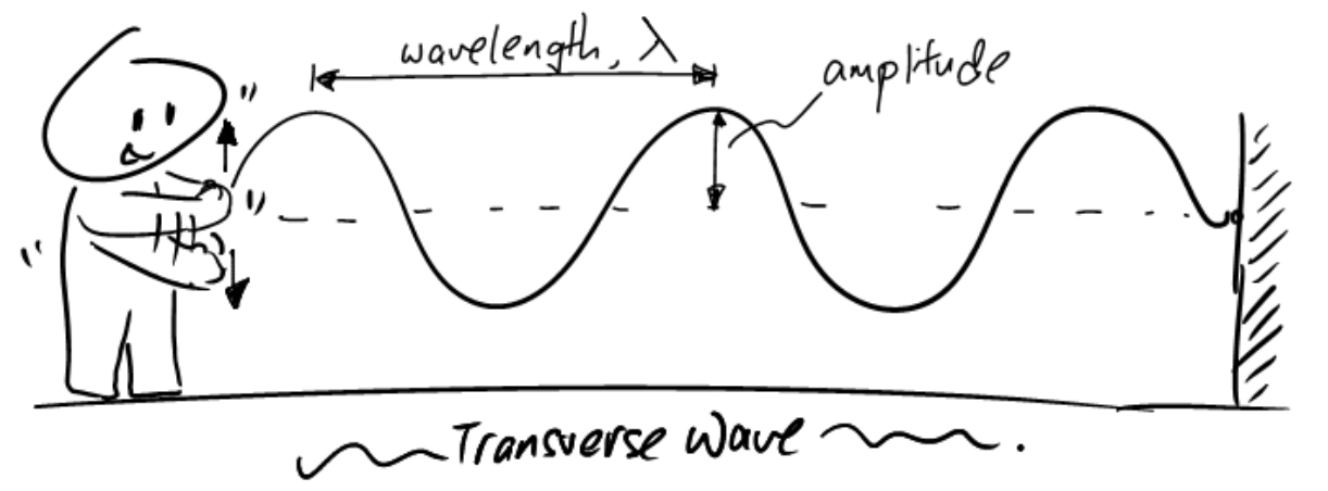
If they are moving to the right like the image above suggest, they can in fact oscillate in any plane providing it is perpendicular to the energy transfer (or sting) itself, e.g.;
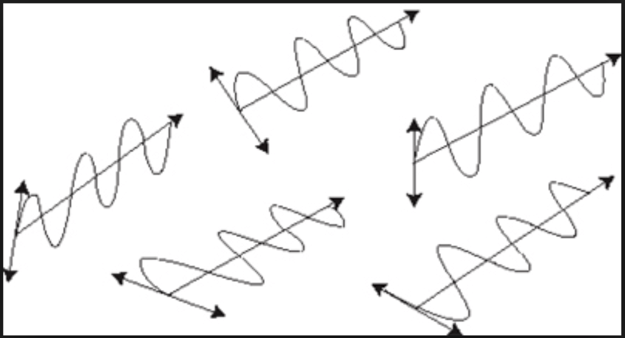
All waves are travelling towards the top right, but the plane of oscillations varies for each.

Unpolarised light can be drawn like the image to the right, this shows the energy transfer going into or out of the page, the oscillations are then in any plane surrounding it.
Polarisers/ Polarised Light
An ideal polariser will polarise all light that passes through it onto one plane. If a polariser were used that polarises light on the vertical axis, it would absorb all horizontal components of each ray passing through it, such that only the vertical component of each individual ray remains in the wave after passing through the polariser. Due to this, the wave that exits the polariser will be polarised on the vertical plane and 

The light can be polarised on any plane – the polariser just needs to be rotated.
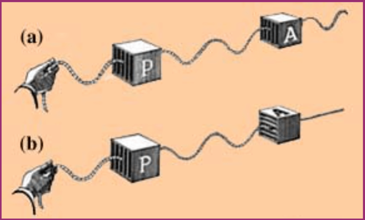
One way to try to image the polarisation of light is to imagine waving a piece of string up and down. This piece of string send the wave along it, the wave then enters a metal grill of some sort, if the grill is orientated such that the metal bars are in line with the vibrations then the wave will continue through – as shown in image (a). If however the bars of the grill are orientated at 

If two polarisers are positioned at
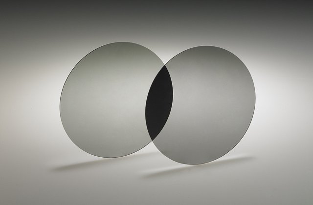
This image shows two circular polarisers, they are orientated such that they polarise light
Any ideal polariser will allow 
Consider plane polarise light of amplitude 


but as we have seen earlier, then intensity of light is directly proportional to the square of the amplitude, therefore the intensity $I$ of the light transmitted through the analyser is given by Malus’s law:

where 

Check out this image in which the colours appear to change depending on the orientation of a polariser placed over the top of it (there is also a polariser under the image):
If you have some more time to read/watch more on polarisation, or if you missed a lesson on the subject then I thoroughly recommend you watch this lecture on Polarisation by Walter Lewin.
Interesting fact:
Some animals can identify polarised light, for example Bees. Some humans can too but you need to be very well trained.
Further reading:
- Isaac Physics – Polarisation – This is a reading resource
- Research the use of polarising filters in polarised sunglasses, 3D cinema glasses and polarising filters for cameras.
- Polarised Light in Science and Nature by J. David Pye
You must be logged in to post a comment.