Objectives:
- To be able to define resistance
- To be able to select and use the equation for resistance
- To be able to define the ohm
- To state and use Ohm’s law
- To describe the I–V characteristics of a resistor at constant temperature and a bulb where the temperature varies (the bulb will largely will covered in the next lesson)
Electrical Resistance
 Now we have an understanding of current and voltage, resistance is a key term to become familiar with.
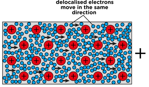 A wire with a current flowing through it will have electrons flowing, with a net direction (mean velocity), and each with some energy (the energy per unit charge being the voltage). However, there are still the ions that exist within the wire. These are fixed into position and do not typically move.
These ions create an obstacle for the electrons to travel around. The electrons ‘collide’ with ions and then transfer some of their energy to them. One way to imagine this is to raise your hand and strike a table with it, upon collision you may feel a small amount of heat (the faster your move your hand the more heat you will feel), instead of your hand consider an electron and instead of the table imagine an ion.
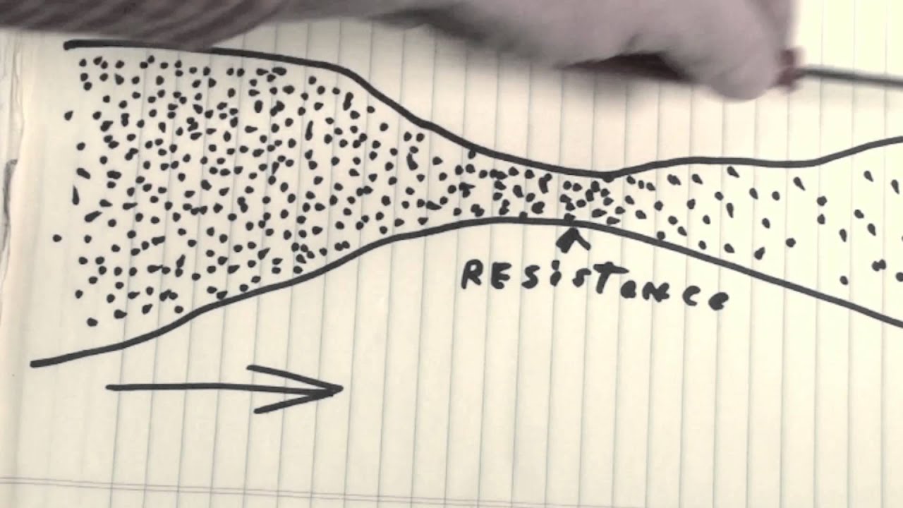
Anything preventing the flow of current or anything that absorbs the energy of the charged particles (i.e. affects the voltage) contributes towards the resistance of the circuit.
Resistance has therefore been defined as ratio of voltage across a component ( 

where;


Resistance is often thought of as an unwanted property in a circuit, however without it, there would be no change in potential difference or current through components and therefore the components would not ‘know’ when to activate or deactivate. What is true is that too much resistance can cause inefficiency in a circuit.
The definition for resistance, 
- If the potential difference increases each unit of charge has a greater amount of energy, which can be transferred to the ions they approach, which can therefore increase the resistance. The equation supports this, if p.d. increases the ratio increases and so the resistance increases.
- If the current were to increase, there would be a greater flow of electrons, which would result in a smaller percentage being affected by the ions (more would pass straight passed without being affected by the ions), therefore the resistance decreases. The equation supports this, if current increases the p.d. will be divisible by a larger current and so the resistance decreases.
Defining the ohm
The Ohm is defined as the resistance across a component when the ratio of potential difference to current through it is equal to 1 volt per ampere; 

Current-Voltage characteristic
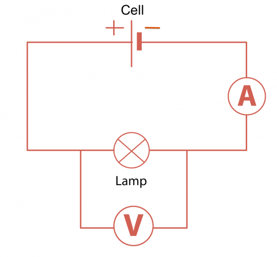
Take a simple circuit as shown here;
If the variable resistor is altered so as to change the overall resistance in the circuit, both the voltmeter and ammeter readings will also change.
If a set of results were taken whereby both positive and negative readings of p.d. and current were collected the following current-voltage graph can be drawn.
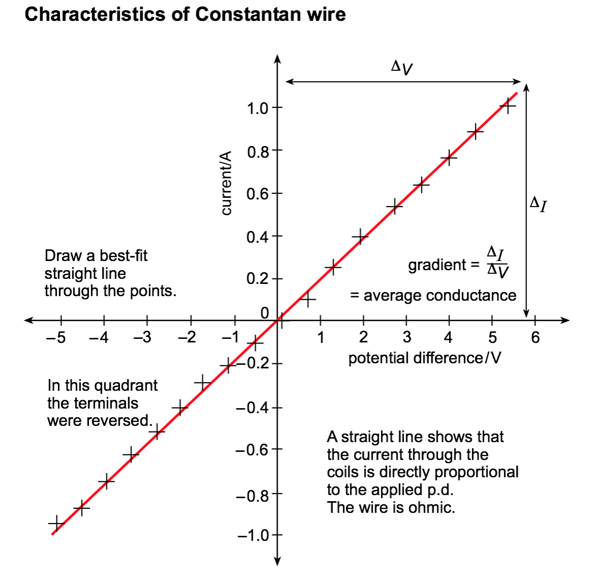 A straight line graph that passes through the origin is drawn, this shows that the current is proportional to the potential difference. This result is known as Ohm’s law, it applies to metal wires whereby the temperature remains constant.
Any point on this graph the resistance can be calculated by dividing the p.d. by the current at that point. If the graph shows a straight line the resistance at any point will be the same – the resistance is a constant. Under these conditions finding 1/gradient gives the average resistance of the wire (graphs using best-fit lines are often the best way of averaging results). Notice the negative quadrant of the graph, the resistance remains constant when the current is reversed.
Ohm’s law

Historically, Ohm showed that the resistance of a metal under constant physical conditions (particularly temperature) is constant. The experiment of passing a varying current through a wire and measuring the voltage across it demonstrates this by generating a straight line graph that passes through the origin: if I is directly proportional to V (or the other way around) then Ohm’s law is obeyed. Any conductor (metallic or otherwise) that behaves in this way is described as an ‘ohmic conductor’.
Wires are known as ohmic conductors because of the straight line through the origin. Resistance is constant at constant temperature.
If temperature varies, the resistance will vary also. In metals there is a lattice of ions with free electrons that conduct the electricity. If it is harder for the electrons to move along the wire because the lattice is vibrating, the resistance will increase. This is the case in a filament bulb. As the voltage increases, the temperature rises in the wire and the ions in the lattice start to vibrate making it harder for the electrons to move along the wire, therefore increasing the resistance.
Further reading:
- Isaac Physics – Ohm’s Law – This is a reading resource
- You should research how overhead transmission cables are constructed and the reasons behind the material choice.
- You should research into the discovery and onset of superconductivity and the potential benefits of room temperature superconductors.
You must be logged in to post a comment.