Objectives:
- To describe how the resistance of a light dependent resistor (LDR) depends on the intensity of light
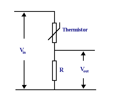
- To describe and explain the use of thermistors and light-dependent resistors in potential divider circuits
- Be able to describe the advantages of using data loggers to monitor physical changes
- Identify techniques and procedures used to investigate potential divider circuits which may include sensor such as a thermistor or LDR
Thermistors
For a full recap on thermistors refer back to the page on them – link.
Thermistors are a type of resistor whose resistance varies depending on the temperature. A temperature – resistance graph for an NTC thermistor looks like;

If an experiment were to be carried out such that a thermistor was kept at a constant low temperature, and varying values of p.d. and current were recorded for it. Then the same process happened but with the thermistor at a higher temperature, the following I-V graph can be obtained;
Light dependent resistors, LDR’s
 LDR’s work based on the same principle as thermistors except that instead of temperature being the variable that affects its resistance it is the amount of incident light on it. As a result the following graph shows the relation ship between increasing light intensity and resistance.

The graph shows the same relationship that a thermistor has to with resistance – only different variables to affect the outcome.
Thermistors and LDR’s used in potential divider circuits

In a case like this, the temperature of the thermistor will have an affect on its own resistance. If the resistance of the thermistor changes then the ratio of resistances changes which results in a change in the distribution of voltages because;
In this particular setup and if the temperature of the thermistor were to increase:
- The temperature increases and so the resistance of the thermistor decreases.
- If the resistance of the thermistor decreases the voltage across the thermistor also decreases, this can be shown using
and
.
- If the voltage across the thermistor decreases then the voltage across resistor
must increase, this is because
.
- Is the thermistors resistance decreases the total resistance of the circuit decreases resulting in an increased current through the circuit. Since;
and
, using
.
The resistance of is constant and so the only factor that can affect $latex IR_{R} $ must be the current, since the current has been shown to increase and the resistance of $latex IR_{R} $ is constant, the voltage must increase across this resistor.
 Temperature devices such as these can be used in a variety of applications from mobile phones and tablets to ovens and fridge freezers. Take a fridge freezer for example, if the temperature gets too hot, then the resistance of the thermistor will reach a certain value which will then result in a larger current through the fixed resistor which could cause the motor in the fridge to work harder to cool the device down.
Further reading:
- Research the difference in design of devices such as volume control, where some use potentiometers and some use resistors in series.
- Electric Circuits by James W. Nilsson and Susan A. Riedel – link
- Introduction to Electric Circuits by Richard C. Dorf and James A. Svoboda – preview link

You must be logged in to post a comment.